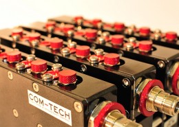
COM-TECH Combiners are designed, engineered, and manufactured with cutting-edge technology in order to grant the maximum reliability and the most advanced performances: highest voltage safety margins, lowest insertion loss, maximum compactness, exceptional mechanical stability and durability.
Manifold Combiners
Cascade of several filters on a common output transmission line (“Manifold”). COM-TECH, after being the first to introduce the Manifold technique to Broadcast TV and FM applications, further extended its versatility exploiting the Adjacency Combination. Cost-effective solution for low power applications, allowing to combine a large number of frequencies.
Starpoint Combiners
Multiple connection of various filters with a common junction. Starpoint combiners are a cost effective solution for a combination of a limited number of frequencies. Adjacency Combination is not generally possible.
Balanced Combiners
Balanced structure of two identical bandpass filters and two hybrid couplers, having one Narrowband (filtered), Constant Impedance input and one Wideband (non-filtered) input. Balanced Combiners offer maximum versatility and performances, allow Adjacency Combination, and permit to create Chain-Combiners.
Features
XLine: Extracted-Pole Elliptical-Response
COM-TECH innovative and proprietary Extracted-Pole Elliptical-Response design, featuring two transmission zeros in a compact, in-line form-factor. Implemented in 6 and 7-Pole CL Series UHF Bandpass Filters. Allows Adjacency Combination in Balanced Combiners.
DualCross: Double Cross-Coupling
COM-TECH innovative and proprietary Double Cross-Coupling design, featuring four transmission zeros. It provides enhanced selectivity, optimum insertion loss and highest efficiency. Implemented in 6 and 8-Pole FC, TF, TC, TS Series Bandpass Filters. Allows Adjacency Combination in Balanced Combiners.
Cross Coupling
COM-TECH innovative and proprietary Double Cross-Coupling design, featuring four transmission zeros. It provides enhanced selectivity, optimum insertion loss and highest efficiency. Implemented in 6 and 8-Pole FC, TF, TC, TS Series Bandpass Filters. Allows Adjacency Combination in Balanced Combiners.
Full-Band Tunability
COM-TECH Filters and Combiners feature state-of-the-art Temperature Stabilization, achieved through 3D EM and Fluid Dynamic simulations, special materials, and environmental and laboratory tests.
Temperature Stabilization
COM-TECH Filters and Combiners feature state-of-the-art Temperature Stabilization, achieved through 3D EM and Fluid Dynamic simulations, special materials, and environmental and laboratory tests.
DC-Short
COM-TECH Filters and Combiners feature state-of-the-art Temperature Stabilization, achieved through 3D EM and Fluid Dynamic simulations, special materials, and environmental and laboratory tests.
Modular Frame System
COM-TECH Modular Frame System allows a complete Combiner modularity, providing an easy and convenient possibility of extension, integration, maintenance and shipment (combiners can be shipped as separate modules, and later assembled and installed on site). It can be integrated with Directional Couplers, Patch Panels, and other components.
Modular Connector System
COM-TECH products feature an innovative and proprietary Modular Connector System, which allows a wide choice of connections to be mounted on the same product. It also permits easy replacement of most connectors by the Customer, at a later stage.
EVA-Mode
COM-TECH innovative design providing the highest Quality Factor in the smallest space, for very compact Bandpass Filters. Implemented on FM CL Series Bandpass Filters, and HE Series Bandpass Filters.
10-Year Warranty
COM-TECH products are known for their reliability. All passive products are guaranteed for 10 years. Active products (E.g. Forced Air Cooling, etc.) and resale products are guaranteed for 2 years.
Options
- Heat Sinks
- Forced Air Cooling
- Liquid Cooling
- Rack-Shelf
Coding
Balanced Combiners Filters use mnemonic codes:
[Product Series: DB, DM, DF] [No. of Poles: 6, 8…] [Design: XLine, DualCross…] [Cavity Size: 80, 110…] [Operating Band: C, B…] / [Number of Filtered Inputs]
- Eg. DB6X50C/2: DB Series, 6-Pole, XLine, 50 mm, UHF, 2 Filtered Inputs (plus one Wideband)
- Eg. DF8D200B/3: DF Series, 8-Pole, DualCross, 200 mm, VHF B.III, 3 Filtered Inputs (plus one Wideband)
COM-TECH Manifold Combiners use mnemonic codes:
[Product Series: MX] [No. of Poles: 4, 5…] [Response: All Pole] [Cavity Size: 20, 30..] [Operating Band: C, B, F] / [Number of Modules]:
- Eg. MX4P20C/5: MX Series, 4-Pole, All Pole, 20 mm Cavity Size, UHF, 5 Modules
- Eg. MX3P120F/3: MX Series, 3-Pole, All Pole, 120 mm Cavity Size, FM, 3 Modules
CHAIN COMBINATION
Balanced Combiners can be connected together to realize Chain-Combiners, also mixing Filters with different Cavity Sizes and Number of Poles, in order to optimize the Combiner chain.
Wideband Port
The Wideband port, available only in Balanced Combiners, delivers a unique versatility to Balanced Combiners, allowing to expand their combining possibility by connecting several Modules in cascade. A chain of n Balanced Modules has n Narrowband inputs and one Wideband input port. The Wideband port can be either be Used (connected to a Filter or a Combiner) to combine additional frequencies, or left Unused (connected to a Load), in order to allow future expansion.
Wideband Port Tuning Optimization
The Wideband port can be either optimized for specific frequencies or for the whole band:
- Frequency Optimized: the Return Loss is optimized for the best values on the specified frequencies, at the expense of reducing the values outside. Extension is limited to the optimized frequencies
- Whole-band Optimized: the Return Loss is optimized to have the best tradeoff on the whole band. Extension is possible, but with limitations on all frequencies
Combiners with MultiStep technique have unparalleled performances, allowing an almost optimal Return Loss value on the whole band.
Extension
A new combiner can be inserted in two possible different positions into the Balanced Combiner chain:
- In the Output (Antenna) side: The new Combiner type must be Balanced, and must be optimized to accept the existing frequencies. The integration requires major mechanical work. The new Combiner is generally bigger
- In the Wideband input: The existing combiner must have its Wideband port Unused, able to accept the new frequencies and withstand the increased power. The new combiner can be Starpoint, Manifold, Balanced (or single Filter). The integration requires reduced mechanical work. The new Combiner is generally smaller
Combination Wideband Power
Tuning data reported on the Datasheets refer to one single Balanced Combiner module. The performances and specifications of Chain Combiners are affected by different factors, such as: number of combined frequencies, frequency order and assortment, and adjacency.
COM-TECH Balanced Combiners have been dimensioned to withstand the overall output power, even in Wideband mode (the Wideband input power having a double impact on hybrid couplers), thus making the calculation of the Wideband Input power extremely easy:
WB Input Power = Maximum Output Power – Sum of NB Input Powers
Combination Peak Voltage
The composition of several digital signals undergoes to a complex statistical process, which deviates from the theoretical voltage composition. COM-TECH Balanced Combiners have been dimensioned to widely sustain the increased voltage peaks caused by the vector composition of several signals (up to 10 frequencies).
Combination Insertion Loss
The overall insertion loss of a Balanced Combiner Chain is the sum of the insertion loss of the single module, increased by the sum of the Wideband insertion losses of the succeeding modules:
Overall I.L. = Single Module I.L. + (n • Wideband I.L.)
Combination Return Loss
The combination of several Balanced Combiner modules involves a derating of the overall Return Loss:
| No. of Modules | Overall Return Loss (VSWR) |
| 1 | 26 dB (1.11) |
| 2-5 | 25 dB (1.14) |
| 6-8 | 24 dB (1.16) |
| 9-10 | 23 dB (1.18) |
Indicative values for Frequency-Optimized Wideband tuning
Adjacency Power Derating
ADJACENCY COMBINATION
COM-TECH has exploited the possibility to combine Adjacent TV Channels (e.g. 21-22-23) or DAB Blocks (e.g. 12A-12B-12C) thanks to innovative techniques: DualCross and XLine Filters, MultiStep Hybrid Couplers, and an improved Manifold combination technique.
Adjacent Channel/Block Combination
Adjacent TV channels (e.g. 21-22-23) or DAB blocks (e.g. 12A-12B-12C) can be combined in the same combiner. Requires a Mask-Combiner configuration (Filters in the transmitters are either absent or removed).
Power Derating
Mask-Combiner / No Mask Combiner
Combiner configuration which makes use of Mask Bandpass Filters (6, 7, and 8-Pole), and consequently Filters in the transmitters are either absent or removed. This approach is mandatory for Adjacent-Channel Combination, and delivers, beyond that, the highest system efficiency, and a complete agility of the transmitters.
Retuning
COM-TECH offers several options for Retuning of its Bandpass Filters and Combiners, with different levels of autonomy for the Customer. Tuning Instructions and Tools are provided upon request. COM-TECH also offers customized Tuning Training Courses.
On-Site Retuning
COM-TECH takes care of the Retuning, limiting the transmission interruption time as much as possible
Factory Retuning
Retuning will be handled in COM-TECH premises with the maximum priority, in order to ship the retuned Component back to the Customer with the fastest time, to reduce off-line time as much as possible.
Substitution Program
COM-TECH Substitution Program permits the seamless substitution of the new Filter or Combiner combiner with the old one, with a very limited Transmission interruption time, and avoiding the retuning to the Customer:
1. COM-TECH ships a new (or refurbished) Filter / Combiner, tuned on the new frequencies
2. Customer substitutes the received Filter / Combiner with the existing one and ships back the latter
3. Once received, COM-TECH evaluates the old Filter / Combiner and refunds it accordingly
Customer Retuning
COM-TECH Substitution Program permits the seamless substitution of the new Filter or Combiner combiner with the old one, with a very limited Transmission interruption time, and avoiding the retuning to the Customer:
1. COM-TECH ships a new (or refurbished) Filter / Combiner, tuned on the new frequencies
2. Customer substitutes the received Filter / Combiner with the existing one and ships back the latter
3. Once received, COM-TECH evaluates the old Filter / Combiner and refunds it accordingly
Remote Assisted Retuning can be offered for simple Filters and Combiners
requires network analyzer hooked up to a fast internet connection, and trained personnel
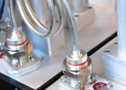
Manifold Cable Change
Manifold Combiners require cables with specific lengths, depending on the frequency set. A frequency change in the chain requires cables lengths to be modified. Beyond offering the Substitution Program, COM-TECH also offers three solutions, providing, thanks to a proprietary Functional Model Simulation, optimized cable lengths for the new frequencies, thus making the retuning of Manifold Combiners straightforward and fast. A lowered wrench, provided by COM-TECH, is necessary for the retuning.
Cables Shipment (Solution 1.)
Simplest and hassle-free solution. When a retuning is required, the Customer purchases from COM-TECH the new cable-set, which is shipped together with the set-up layout. The Customer needs to retune the combiner modules, and, once received, apply the cables according to the set-up layout.
Premade Cable Kit (Solution 2.)
Simple and immediate solution. The Customer purchases, in advance, from COM-TECH a kit of premade cables of varied lengths. When a retuning is required, COM-TECH provides the calculated cable lengths for the new frequencies, together with the set-up layout. The Customer needs to retune the combiner modules, pick the cables with the communicated lengths and apply them according to the set-up layout. The cables kit can be reassorted just purchasing the cable lengths needed.
Cable Assembly (Solution 3.)
Completely autonomous solution. The Customer purchases , in advance, the Manifold cable connectors (from COM-TECH) and the spare cable (either from COM-TECH or a local Seller). When a retuning is required, COM-TECH provides the calculated cable lengths for the new frequencies, together with the set-up layout. The Customer needs to cut the cables at the communicated lengths, assemble them, retune the combiner modules, and apply the assembled cables according to the set-up layout.
Operating Conditions
Standard Power Ratings
Power ratings reported in the Datasheets refer to the following standard conditions:
- Altitude: below 1.500 m (4.900 ft.). (See Altitude Thermal Derating and Altitude Voltage Derating)
- No Rack-Shelves, no enclosures, no obstructions to natural air convection
- Heat Sinks: fins in vertical position, and no obstructions to air flow
- Liquid Cooling: Glycol 30%, Temp. 45 °C (113 °F), Flow 6 l/min (1.6 gal/min)
- Combiners: No Adjacencies
- Body temperature below the maximum operating value (Typ. 65°C, 149°F, See Product Datasheet)
|
Altitude
|
Relative Power
|
|
0 – 1.500 m (4.900 ft.)
|
100%
|
|
2.000 m (6.500 ft.)
|
96.7%
|
|
2.500 m (8.200 ft.)
|
93.5%
|
|
3.000 m (9.800 ft.)
|
90.2%
|
|
3.500 m (11.400 ft.)
|
86.9%
|
|
4.000 m (13.000 ft.)
|
83.7%
|
Filters and Combiners may undergo an additional power reduction due to decreased dielectric strength of rarified air, which affects their voltage safey factor. The altitude voltage derating depends on their design and it is typically impacting when operating at high power with Forced Air Cooling and Liquid Cooling options. COM-TECH carries out specific calculations when an installation at high altitude is involved, in order to maintain a high voltage safety factor.
COM-TECH products conform to the following Operational, Transport, and Storage conditions:
- Operational Conditions: ETSI EN 300 019-1-3 V.2.4.1 (2014-04), Class 3.1, Normal Conditions
Maximum Operating Temperature: see Product Datasheet - Transport Conditions: ETSI EN 300 019-1-2 V.2.2.1 (2014-04), Class 2.2
- Storage Conditions: ETSI EN 300 019-1-1 V.2.2.1 (2014-04), Class 1.1
COM-TECH products are designed for indoor use, and are not waterproof. Maximum attention should be carried out to prevent contact with water, especially during transportation and installation.